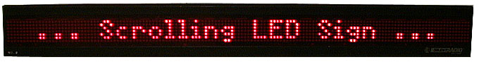
Scrolling LED Sign
Index:
About:
I have always wanted a scrolling LED sign that I could program with whatever message I wanted. I had schemed about various ways to design one using a ton of logic circuitry and LED buffer/drivers. Fortunately, at a trip to the First Saturday Sale in Dallas in 1999, I managed to pick up a junked one for $10US. After some brief testing, it was concluded that the power circuit was completely shot. I concluded that it would be best to try and scrap the power and control circuits and create my own from scratch.
The result? Reverse engineering the display portion of the sign to create a custom driver circuit and supporting software. I designed and built a custom driver circuit by hand, from scratch. I then etched a PCB and mounted it directly inside the sign chassis where the old controller board was located. The LED sign is currently wall-mounted and connected to the internet.
Description:
The real core of the LED sign project is the custom driver circuit. This circuit uses a Microchip PIC 16f628 microcontroller for control purposes. The PIC processor uses memory-mapped memory to control sign display bits. Essentially, the PIC chip has display memory mapped into its internal RAM. The PIC microcontroller controls the LED sign via 7 NPN column drivers and some additional I/O pins for shift register signaling.
A master host PC communicates with the PIC via RS232 serial communications. Commands to read and write memory locations on the PIC have been implemented, in addition to functions for clearing and shifting memory. In this scheme, the host PC thus has total control of the display memory.
A set of Perl scripts was written to manage the PIC memory and output useful information to the LED screen. The Perl code uses font files from the figlet project to map ASCII characters into 2-D bit arrays for display purposes. Additional Perl functions were implemented to do various character animations and display effects. Furthermore, Perl routines were constructed to display useful information (some of which is pulled, in realtime, from the internet) in various pretty ways -- including time, weather conditions, server usage statistics, and headlines.
A web interface to the sign is in the works, as is a live, possibly streaming webcam view for realtime display across the internet.
LED Sign Images
The image below try to display the LED sign progression from start to finish. There are probably some seriously important stages missing, such as the development breadboard. Oh well, I tried. Click any of the following images for greater detail.
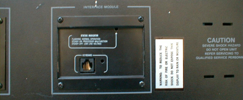
These show some details of the sign, such as the manufacturer label, power interface connector, and keyboard interface connector. These were taken soon after I purchased the sign.


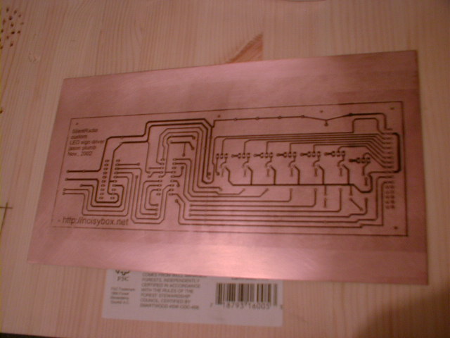
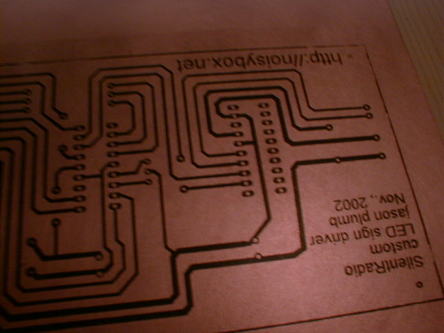
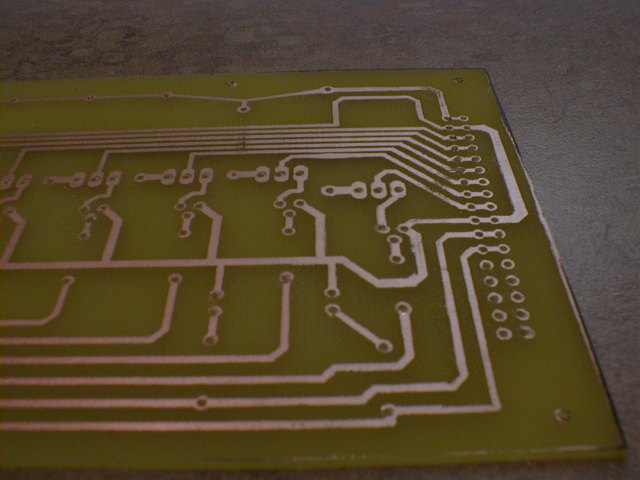
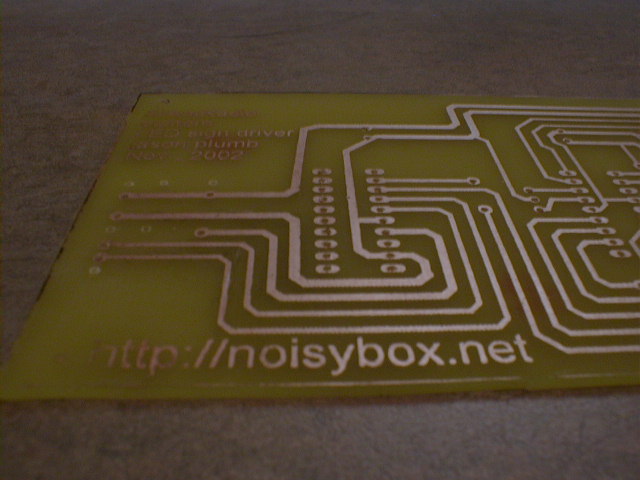
Some various stages of circuit board development, from iron-on through etching and drilling:


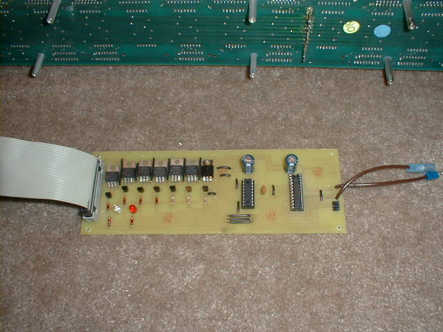
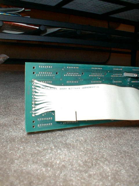
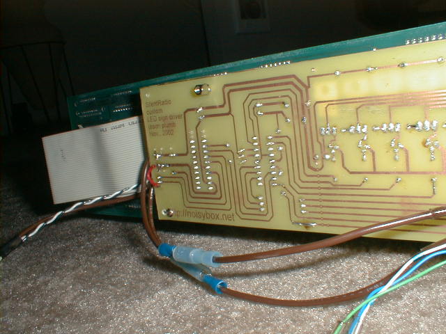
Finished printed circuit board, sign internals, mounting, and wiring harness(es):


Some images taken when the sign was first deemed "working":

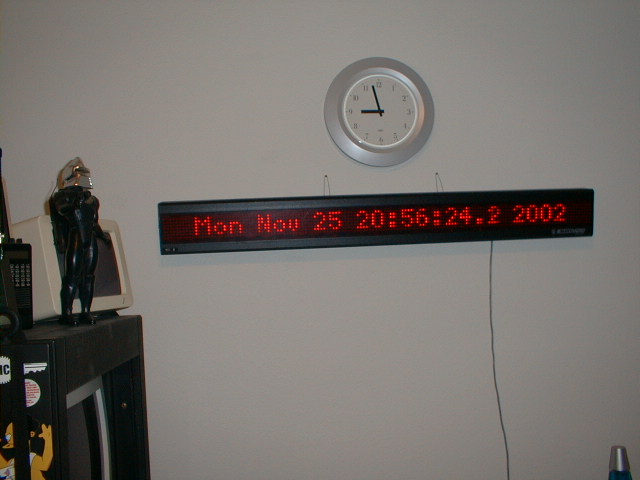
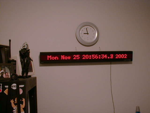
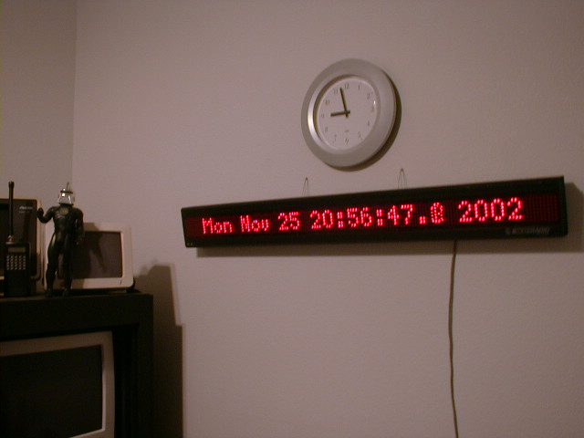
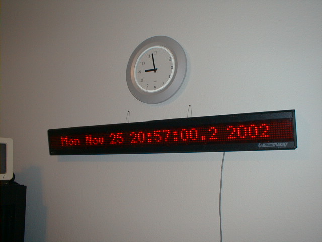
Completed sign hanging on the noisybox.net laboratory wall:
LED Sign Hardware
- The LED matrix and driver hardware has been reverse engineered. A hand-drawn image of the sign's display circuit can be found here. Thanks to John Walter for the help in creating this diagram. I've also updated it in the year 2021 -- now it's easier to read! Sorry it was so awful for so long.


A horribly ugly (and probably somewhat inaccurate!) hand-drawn image of the controller circuit I designed and built is here. Not going to update that piece of shit, because I'm making a new board in 2021. Woah.

- LED driver circuit (on which the LED matrices themselves are soldered) functions by sweeping a column bit across some shift registers and toggling the appropriate row bits. If all goes well, this happens faster than the human eye can perceive.
LED Sign Software
The LED sign software consists of 3 main components:
- The PIC assembly code. This code runs on the microcontroller and is responsible for refreshing the sign from the mapped memory (RAM). It talks an RS232 (serial) protocol to get updates to its display memory.
- ledsign.pl - Perl code to control the sign. Responsible for doing text/font mapping and conversion to serial. Also responsible for doing "special effects" and has an interactive mode.
- ledctrl.pl - Perl code to schedule interesting messages. Fetches feeds and calculates messages that should be displayed.
Some older thoughts, back when the sign was under development. Kept here for posterity:
Version 1:
A block of RAM (probably have to split between banks) will be mapped to the display. All character conversion/mapping and control will be done via PC and serial port. Now that I have a PIC with a built in UART, I think it's much more possible. Let's check some math:
145 columns == 145 RAM locations == 145 bytes
To do 25fps (full LED screen animations) all controlled by PC through serial port, we need
25 frames/sec * 145 bytes/frame == 3625 bytes/sec required throughput.
So..... 3625 bytes/sec * 10bits/byte [rs232 start stop bit overhead] = 36250 bits/sec required throughput.
If a single RAM location takes 2 bytes to write (this may not end up being the case, but let's assume here that there are no block transfers and every column is addressed individually by the PC), this doubles our requirements to:
72500 bits/second
Which means that if 115200 can work reliably (I'm reasonably sure that it does with a MAX232/3), this is quite possible... or we take a speed hit at 57600 and get choppier animation effects.
Working backwards:
115200 bits/second * 1 byte / 10 bits = 11520 bytes/second
11520 bytes/second * command / 2 bytes = 5760 commands/second
5760 commands/second * screen / 145 commands = 39.7 screens/second
If this can be achieved, I can certainly live with it...
Implementing a block-fill command could nearly double this rate (bytes/command -> 1)!
This also assumes that the communications overhead is negligible and won't effect display performance. I guess we'll see...
RS232 protocol specification:
So here are some preliminary thoughts about how the PC-to-PIC protocol might work:
From PC to PIC: b1 b2
All PC to PIC commands are two bytes.

If b1 is in the range (1..145) then it should be taken as an address,
and b2 should be considered data.  This is the primary mode of operation.

b1 can also be one of the following special case command values, some of
which may be considered optional and may never get implemented:

200 - Read data at addr b2\.  PIC replies with single byte data value.
    PIC maps b2 to be in range, so out of range requests will
    yield undefined return values.

201 - Shift RAM left, number of bytes to shift in b2\.  This can be used
    to simplify scrolling horizontally.  Always shifts in zero (0).

202 - Shift RAM right, number of bytes to shift in b2\. This can be used
    to simplify scrolling horizontally.  Always shifts in zero (0).

203 - Shift in from left, single byte b2.

204 - Shift in form right, single byte b2

205 - Invert entire display, b2 is ignored.

206 - Initiate block load transfer number of bytes in b2.
    PC sends b2 bytes back to back, PIC starts loading at display
    location zero. Helpful in doing full frame animations?

207 - Blinky, b2 = 0 to turn off display, b1 = 1 to turn back on

208 - Invert single byte at location b2.

209 - Fill entire display with value b2.

-----------
optionals (ie. things I probably won't do):

??? - Get brightness, b2 is ignored.  PIC replies with single
    byte value of current brightness.
??? - Set brightness control, b2 indicates brightness, probably has
    limited range.
Other thoughts:
- Get back to "SilentRadio" roots -- news, headlines, etc.
- Date, time, uptime, server load, etc.
- Time limited web interface to "draw" pixels on LED screen
Conclusions:
[Some final thoughts, what I'd change, and some links to stuff with historical significance]
Links:
[There will be links here to relevant resources]
Revision History
NOTE: This history was originally just a place for me to make some notes during the development phase. Now that this project is nearing completion, it is unlikely that this section will ever change (much)
02/07/04 - I added Yahoo Buzz RSS feeds to the LED sign controller app. I will now get regular updates that keep me informed about what the rest of the world cares about. :) I also took a little time to fix a few small bugs and added two new display effects: clear wipe from left and clear wipe from right. Nothing amazing, but just a nice touch.
04/03/03 - I managed to do some work today and yesterday on reorganizing this page. It should be a little more coherent, but probably still needs additional work and a bit more content that's already available. The Perl scripts got some attention also -- it now uses a socket (allowing for bidirectional communication) and can display Slashdot headlines in addition to random short fortunes.
12/18/02 - I spent some time tonight hacking on more Perl code for the sign. I added one new display effect and fixed a pretty significant display bug related to the time display routine, in addition to making the code a bit more flexible and improving control over timing (speed) parameters. I'd still like to add some more display effects... I also realize that this page is is really lacking in some details... so hopefully soon I'll get around to posting the PIC code, a scan of the circuit, and even artwork.
I've still got some work to do, but the sign currently displays time, weather every 30 seconds, and server uptime stats every 2 minutes. I'll certainly need to tweak the time parameters some, and I'd like to So far so good...come back for more soon!
11/25/02 - No updates for the last few days, but really, lots has happened. The board was finished and mounted inside the LED sign chassis. I guess I forgot to take some pictures of the nice fitting grommet installed in the removable back panel.
I struggled with some damn weird problems for a while before discovering that the silly "brown-out" function was disabled and causing the PIC to reset under certain circumstances. Stupid. When I cleared the configuration bit, things went smoothly.
The LED sign is now mounted in the lab, right under my clock.
Apparently a few of the pictures caught the sign in mid-digit-change. You can see a weird looking tenth-of-a-second digit in a couple of the pictures. I suspect that the shutter was open during at least two refreshes.
The only real thing left is pc-side code. I've been writing a lot of perl to do some different things with the sign. Some of these so far include scrolling messages left, right, up, down, random pixel fills, random pixel dissolves, time display (as seen in the above pictures), and some other things. Everything is still entered manually (except for the running time display) through the perl script I wrote. Very soon I'll be ready to handle data from an external source. Once I'm happy with the way things are running, I'll try to take some video captures and put them up for your viewing pleasure!
11/21/02 - Well, when the sign is really done and wall mounted, I'll have to do some cleanup on this page. :)
I made a pretty little printed circuit board for the sign today. I used the iron-on-transparency method, and, to my total surprise, it actually worked damn well! Here are some pix...
The holes were all drilled by hand very quickly, so the alignment of some holes leaves something to be desired. Some of the parts pads should have also been bigger, but damn if I could figure out how to do it (easily) in Eagle. Oh well! The quality of the board is really great! I probably either didn't leave the iron on long enough or press hard enough in a couple of places (pic 5 shows these spots the best), but even then, it turned out nicely. Certainly nothing that a little solder won't cover.
If you're ever going to make a PCB with the iron-on-positive-resist method, I suggest: 1) press the iron hard and take your time. 2) heat the etchant in a bottle submerged in very hot water (this greatly reduces the etching time, at least it did for me). 3) Agitate, agitate, agitate (helps to get an even etch and speeds up the time)
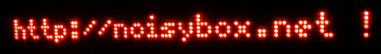
Oh yeah, and yesterday I got an on-boot loaded into the PIC code. On power up, the PIC will show "http://noisybox.net" centered in the display.
11/17/02 - More updates on the sign. I got a piece of sheet metal cut to fit over the exposed end. After cutting a notch in the broken off screw jammed in one of the tapped holes, I could get it out with a flathead. A coat of flat black spraypaint on the sheet metal and the holes, and it actually looks fairly decent.
Made some pretty decent firmware upgrades too. Arbitrary shift left and right, shift in left byte and shift in right byte, and invert display are now all implemented in firmware. I sped up the screen refresh rate a little too, and it seems to help the scrolling display look less "jerky" (it's running around 70Hz right now).
I hacked around on some more perl code to drive the sign, and now have working routines to do quite a bit of stuff (I'll post a version of the script up here fairly soon). I ran into a very strange problem with one of the scrolling routines. Still don't have it working exactly as desired, but I managed to hack around it for the time being. Hopefully I'll revisit the issue later.
Finally, I got my new power supply (capable of 1.8A at 5V) running the sign. The supply seems to work a little better, but honestly it's a little tough to say for sure. I also sketched out the circuit by hand, so that doing an actual board layout should be easier.
11/15/02 - Well, it was late last night, but IT'S ALIVE!
You can check out another "it's alive" message HERE. I'm now able to control the sign and send custom messages to it from the PC via RS232 at 115200 baud. I'm stoked.
A couple of other notes: I need to get a board made so I can get the circuit off of breadboard and into the chassis. I'm hoping to use the existing standoffs inside to get a nice, low-profile mount. I need to cut up a piece of metal and cover the open right-hand side. And add panel mounts for serial cable and power connector. And probably reduce the ribbon cable length. And load a canned message into RAM from flash on boot. And implement a few more useful PIC commands, such as shift and clear and bulk load. I'm currently using some fonts from the figlet project, but they need a massaging to look "just right" on the sign. I need to work on those a bit more too. And once I've done all that it's just more PC side scripting.
11/11/02 - Got the latest version of the PIC code loaded. I can now communicate with the PIC via interrupt driven serial port at 115200 baud. Routines are in place to read/write a 145 byte RAM buffer split between banks 0 and 1. The bank switching makes things a little messy, but it's working. The goal here is to use the 145 byte buffer as a display buffer, updated by the PC serial port. I have a little text-based interface written in Perl to read/write/fill/dump the display memory. I suppose the next step is going to be implementing a display timer and then mapping the display memory to the physical LEDs.
11/11/02 - Wow, I managed to pick this project back up after 2+ years of neglect. I'm working on some new software for the PIC16f628. I'm also adding some notes below regarding operation... So far, I've managed to get an interrupt-based version of some PIC code running with the UART on the 16f628. I also hacked together a perl script to read from the serial port in Windows to help in development/troubleshooting. It seems that Perl can handle reading from the serial port at 115200, unfortunately the stupid command prompt DOS window can't scroll text that fast....so go figure.
6/25/00 - I've updated this web page. It really hasn't had much updating since it was originally created. I'm doing this in hopes of providing better documentation on the project's status.
6/24/00 - Speed problems. The driver circuit seems to have some speed issues. As the refresh rate is increased, the brightness of the display goes dimmer. I'm now convinced that the circuit needs reworking.
Pre 6/25/00 - The original index page has been preserved here. If you have any interest in reading what it said, follow the link.