Arcade Gate
March 2018
About
In February 2018 I found some arcade switches from a prior project and decided to put them to use. I had been wanting to DIY some lofi eurorack modules and figured a manual gate would be handy, so I got to work.
The Build
Here's what I did:
Conception
I had seen a module with an arcade button in it before, but I wanted to roll my own. I found 3 switches, and wanted to work them all into the design. I also wanted to do this without a PCB -- so it meant keeping things simple. Each button would just provide a rising gate to 5V, unless an input was plugged in, and then it would route the input to the output. 3x. I later decided that the middle button should route between two different inputs, while still defaulting as a rising 5V gate without inputs.
Layout
In order to see how things might fit together, I measured all the parts and laid out a panel in Inkscape.
Aluminium
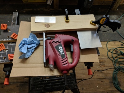
Next, it was time to source some aluminum panel. I bought a 12"x12" sheet of T6 6061 (.063" thickness) and assumed that I could end up cutting multiple panels from that size over time. I made a really stupid jig in order to use my jigsaw with metal cutting blade. The jig allowed me to a cut a strip of aluminum at the correct height, and then I came back and cut that strip into the correct width (the panel ended up being 10HP, or 2").
The jig allowed for a pretty decent cut, but as we all know, jigsaws suck and almost never leave a great result. I used some random oil I had in the shop, and I'm sure it helped lubricate somewhat, it wasn't the right stuff.
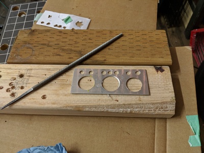
I cleaned up the edge a bit with a bastard file and it turned out quite good.
Drilling
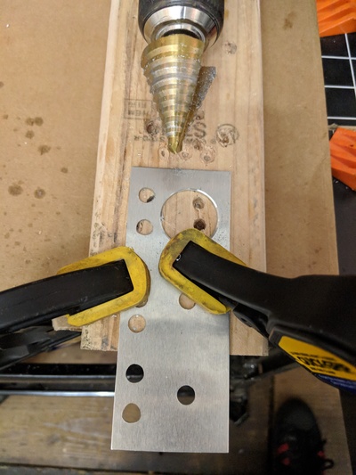
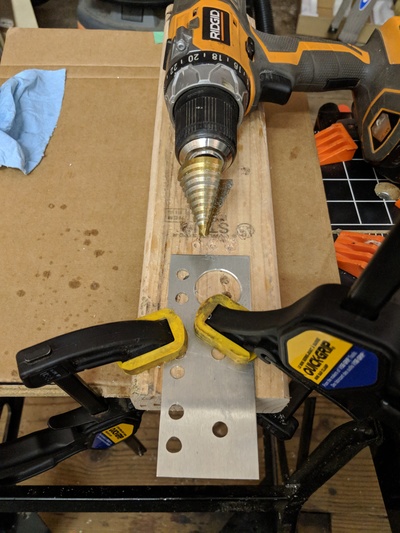
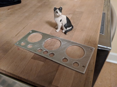
There were 10 holes that needed to be drilled: 3 large ones for the arcade buttons, and 7 for 1/8" jacks. I probably should have used a drill press, but I don't own one and I just decided to go for it. The process was basically:
- Use a center punch in the middle of each hole
- Clamp the hell out of it
- Lubricate
- Try and hold the drill straight
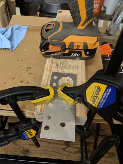
The aluminum gets very hot, so I had to take breaks and let things (including the drill) cool down some. Definitely got burned at least once. :) You may also notice that some of the rubber from the clamps melted and stuck to the panel. Whoops.
After the holes were drilled, there were some rough edges that needed to be filed down. I cleaned those up with two different sized files, and then lightly sanded both sides of the panel.
(* note: cat not to scale)
Dry Fit
To ensure that things were still going well, I put the hardware into the faceplate and spot-checked it against the actual mounting rails. Seemed to be pretty good. The pictures don't show it, but I used a blank 10HP faceplate to mark the mounting holes and center punched and drilled them.
I was pleasantly surprised that things lined up pretty well. Not perfect, but perfectly functional.
Wiring
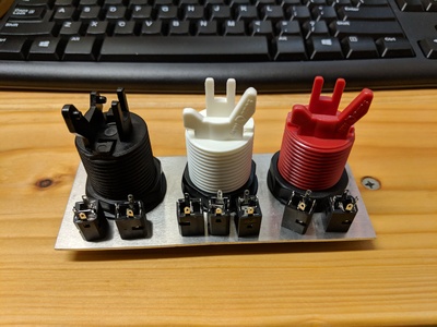
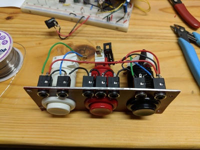
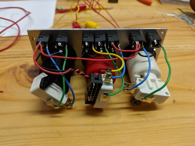
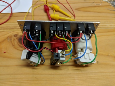
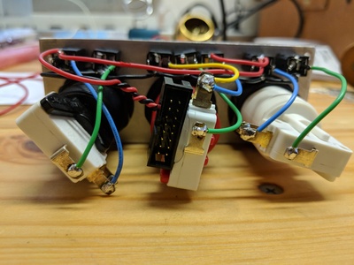
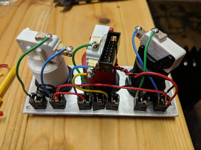
Time to start soldering things together:
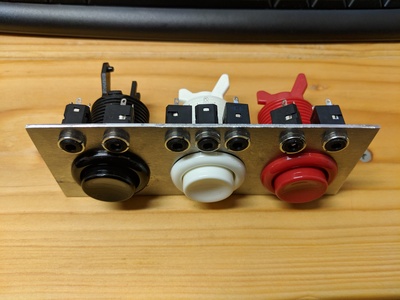
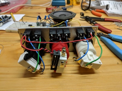
I used the multimeter a lot to check things out along the way. Notice that the power shroud connector is just hot-glued to the side of the middle switch. Seems fine (for now at least).
Finished
Final wiring complete:
I used the red background version of the faceplate, and glued the paper to the aluminum and then hit it with 1-2 coats of clear acrylic spray.
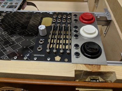
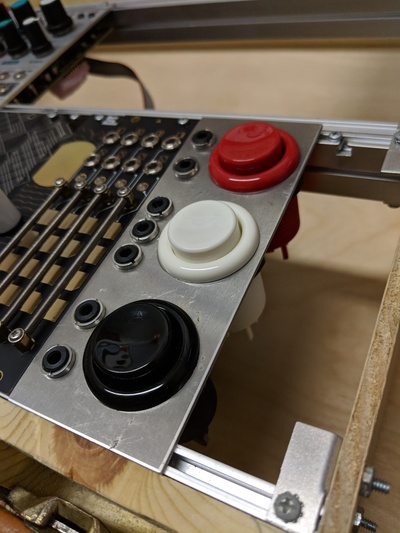
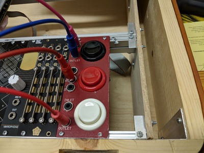
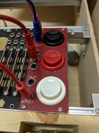
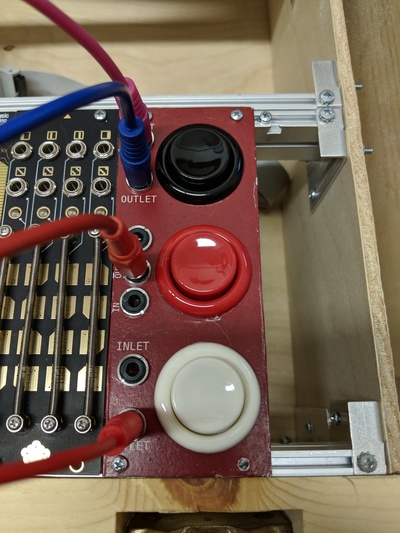
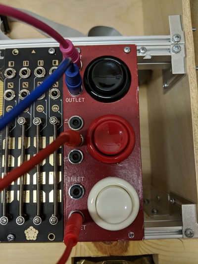
Finished and mounted on the rails:
Conclusion
There's always something to learn from making! Let's see...what would I improve for next time?
- The paper sucks. I really needed (wanted?) labels, but the paper just turned out looking kinda crappy. Maybe laminating first and then using a more industrial glue could have helped? Next time I might just try transfer labels or even sticker material instead.
- The acrylic spray was the bottom of the can and it was below freezing. Turned out bumpy and junky.
- It's stupid to leave the gate floating when the switch isn't pressed. Even though it's working for now, I still need to add pull-downs to the gate outputs.
- Should have added LED for visual indicator
- Hot glue is probably not great
- I haven't looked at them on a scope, but the switches are probably bouncy. A small cap could helped to debounce, but I couldn't be bothered.
- Use the right cutting oil! I think the drilling would have gone much easier with the right kind of oil.
